
Since 1991

This series of controller is suitable for the automatic adjustment device of capacitor compensation device in low-voltage distribution system,with high-performance microprocessor as the core device,sampling physical quantity for power factor and reactive power in two optional modes,fundamental wave sampling against high harmonics of the grid,so that the power factor of the grid is stable in the range specified by the user,which can be widely applied to different grid conditions.
Brief Introduction
This series of controller is suitable for the automatic adjustment device of capacitor compensation device in low-voltage distribution system,with high-performance microprocessor as the core device,sampling physical quantity for power factor and reactive power in two optional modes,fundamental wave sampling against high harmonics of the grid,so that the power factor of the grid is stable in the range specified by the user,which can be widely applied to different grid conditions.It is developed by our company with more than 30 years of reactive power compensation control technology and has independent property rights.
The controller with communication function can be customized,moreover,it is an IOT product,which can be monitored remotely (through computer or cell phone).
This product conforms to the standard:JB/T9663 (our company is the main drafting unit of this standard)
Feature
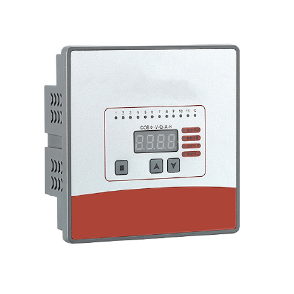
1.Friendly human-machine interface,easy to operate can display power factor,current,reactive power,voltage;
2.Adopt high-performance CPU chip,integrated motherboard,overcoming the traditional controller 3 pieces of circuit board brought about by the wiring complex,easy to false welding or poor contact and other faults,more stable and reliable operation;
3.Adopting self-learning intelligent measurement and control technology,the power factor mode can automatically measure the user's external transformer ratio and the capacity of each capacitor from 1 to 12 ways,and the C/K ratio is automatically detected without manual setting.
4.With low reactive power automatic blocking function,effectively preventing the throwing oscillation and improving the service life of contactors and capacitors.
5.Adopt AC sampling technology;Anti-harmonic and resist peripheral common mode amplitude 2000V pulse interference.
6.Adopt new data detection control technology,detection more accurate,overcome the traditional controller low power factor,small current or over current under the easy detection error,false throw or non-throw situation;
7.With power factor and reactive power two control modes,a machine with multiple uses,high control accuracy,full functionality, convenient for users to choose or replace other models;
8.All kinds of control parameters are adjustable digitally,easy to use,no loss of data in power failure;
9.With automatic operation and manual operation of two working modes;
10.With overvoltage and undervoltage protection function, to prevent capacitor damage under overvoltage;
11.Can automatically identify the polarity of the sampling current, without the worry of wiring errors;
12.The controller has the function of self-test and reversion,which can be done by self-test and reversion of output circuit;
13.It can set the delay time for capacitor re-installation to ensure that there is enough discharge time before the capacitor is put in again;
14.The capacity of each circuit can be set arbitrarily,and the system can automatically adapt to 11 kinds of coding throwing modes; with a variety of throwing modes, such as cyclic,coding and seeking,to reduce the number of throwing times and improve the service life of the compensation device;
15.The number of output channels can be set,and each channel can be closed or fixed direct throw,which can be used for transformer no-load in-place compensation;
16.When customizing the communication function,it can realize the four remote functions such as telemetry,telematics,remote control and remote adjustment through computer or cell phone.
Technical parameter
Working Mode:Power factor or Reactive power
Rated voltage:AC 230V/400V±20% Rated current:AC 0-5A
Frequency:50/60Hz
Insulation voltage:690V
Sensitivity:50mA
Protection level:IP30,panel IP40
Output:AC220V/5A or 380V/3A each channel(Node);DC12V/20mA each channel(Active);
Altitude:<2500 meters;
Temperature:-30°C~+50°C;
Humidity:<50% (@40°C);<90% (@20°C).
Environmental conditions:No corrosive gases,No conductive dust,No flammable and explosive media,No violent vibration.
Model
|
Model |
Output Method |
Voltage(V) |
Hole Size |
Communication |
|
JKW-2SC/3SC-12J |
Node output |
Line 400 |
113x113 |
NO |
|
JKW-2SC-C-12J |
Node output |
Line 400 |
113x113 |
YES |
|
JKW-2SB-12J |
Node output |
Line 400 |
162x102 |
NO |
|
JKW-2DC/3DC-12J |
Node output |
Line 400 |
113x113 |
NO |
|
JKW-2DC-C-12J |
Node output |
Line 400 |
113x113 |
YES |
|
JKW-2DB-12J |
Node output |
Line 400 |
162x102 |
NO |
|
JKW-3SC-12D |
Active output |
Phase 230 |
113x113 |
NO |
|
JKW-3SC-C-12D |
Active output |
Phase 230 |
113x113 |
YES |
|
JKW-3SB-12D |
Active output |
Phase 230 |
162x102 |
NO |
|
JKW-3DB-12D |
Active output |
Phase 230 |
162x102 |
NO |
|
JKW-3DV-12D |
Active output |
Phase 230 |
113x113 |
NO |
|
JKW-3DC-C-12D |
Active output |
Phase 230 |
113x113 |
YES |
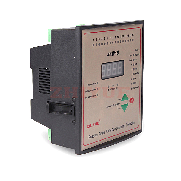
Key Function
|
|
|
|
|
|
Display description
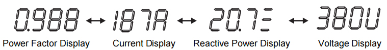
Note:Under the power factor mode,the CT value is not set,so the current and reactive power are displayed as secondary values.
Indicator Description
Parameter setting instructions
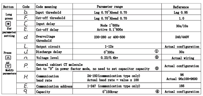
Note: ① In order to protect the capacitor,there is a discharge time after excision, so a certain delay is needed when it is put in again.
②400V voltage level (voltage level fixed) indicates voltage sampling BC wiring,230 voltage level indicates voltage sampling AN wiring.
③0 means power factor mode, no need to set capacitor capacity,and the displayed current and reactive power are secondary values; greater than 0 means reactive power mode,need to set capacitor capacity, and the displayed current and reactive power are primary values.
The value is the total cabinet CT numerator value,such as 500A/5A,then it can be set to 500, and cannot be set to 100.
④The reactive power mode is proprietary. q1, q2, . . q9, qA, qb, qc indicate circuit 1,circuit 2...The capacitor capacity of circuit 9,circuit 10, circuit 11,and circuit 12.
The display value is indicated by two digital tubes, and for values over 99, the high position is indicated by letters.A,b,c,d,E and F indicate 100,110,120,130,140 and 150 respectively.
For example,q1.A5 means the first capacity is 105,and qc.E9 means the twelfth capacity is 149.
After setting the capacity, the system will automatically adapt the coding method,if it can adapt the coding,the system will cast and cut according to the coding method,if it cannot adapt the coding,the system will cast and cut according to the non-coding method.The built-in coding methods of the system are1:1:1:1:1,1:2:2:2:2,1:2:4:4,1:2:4:8:8,1:1:2:2:2,1:1:2:4:4,1:1:2:8:8,1:2:3:3,1:2:3:6,1:1:2:3:3,1:1:2:6:6 and so on 11 kinds of coding methods.
Special case:set to 0,the circuit does not participate in the throwing,such as a road damage can be set to 0 to close the road;set to FF,the
circuit has been in the input state,can be used for fixed compensation.
Installation and commissioning
1. Parameter modification:Press and hold for 3 seconds to enter the parameter menu,then click toselect the function code to be modified,press to increase the value,press to decrease the value, after the parameter is modified, long press display exit and save the settings,if no operation within 5 minutes, it will automatically return to the automatic state;
2. Manual operation: By default, the machine is in automatic operation state. Click to enter the manual operation mode.The manual indicator light is always on.Press to switch on the capacitor, press to cut off the capacitor, and then click return automatically;
3. Complete set of factory debugging,generally only need to modify the number of circuits,the total cabinet CT and each circuit capacity,manual throwing to determine whether the output circuit is connected correctly,automatic by the conditions of the test is not easy to focus on checking the product wiring voltage phase and current phase is connected correctly,check whether the capacitor cabinet voltage phase is consistent with the total cabinet phase, check whether the total cabinet CT is placed in the capacitor cabinet before the main incoming line to check the controller Check whether the display current is consistent with the total current (secondary current is displayed in power factor mode;primary current is displayed in reactive power mode, and the sampling transformer is set to molecular value);
4.When the voltage is higher than the overvoltage setting value,the overvoltage indicator lights up,and when the voltage is lower than 0.8Un,the undervoltage indicator lights up,and the capacitor is gradually and quickly withdrawn from operation within 60 seconds.
5.When the low reactive power indicator is on,it means that the current power factor is lower than the input threshold setting value,and the current grid reactive power to be compensated is less than the capacitor value of the compensation cabinet,although the power factor is lower than the target value,but the controller enters into the low reactive power blocking protection function in order to avoid throwing oscillation and protect the capacitor service life,it is normal not to put in under such circumstances,and will continue to work automatically as the load increases.
6.The controller shows means the user load current is very small, no-load or no sampling current, and the transformer circuit is abnormal;
7.When it is not over-voltage,under-voltage,under-current and in automatic operation,if the power factor of the grid lags behind the input threshold and the reactive power is higher than the C/K automatic monitoring value or the minimum capacitor value,the pre-input indicator lights up and continues to exceed the input delay time setting value, then it is put in all the way;if the power factor of the grid If the power factor of the power grid is ahead of the removal threshold,the pre-removal indicator lights up and continues to exceed the removal delay time setting value,then break off one way;if the power factor is greater than the input threshold and less than the removal threshold, then neither input nor removal,maintain the status quo;
8. If the user load changes faster,it is recommended to give priority to the reactive power mode,set the transformer ratio,capacitance capacity of each way (you can input the actual compensation capacity),in order to make the compensation effect more ideal.
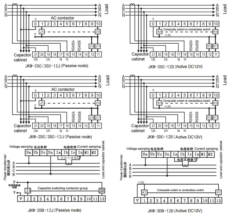
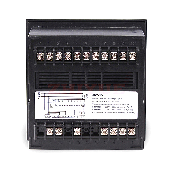
Wiring diagram
Faults and troubleshooting
1. The controller shows put in, but the contactor does not act or the compound switch does not conduct The 12-way indicator on the controller operation panel has been lit, but the contactor does not act, you should check whether there is voltage between the controller output V terminal and the contactor coil terminal, or whether the voltage matches with the contactor coil voltage, the compound switch does not conduct, please check whether the trigger signal is connected backwards or open; or the compound switch output is not connected to the capacitor.
2. With the capacitor input but the power factor does not change much With the capacitor input, the capacitor cabinet current keeps increasing, but the controller power factor hardly changes or changes little should check whether the installation position of the sampling CT is correct, it should be able to monitor the load current and the capacitor cabinet current at the same time;.
3. the displayed current value, reactive power value is too different from the actual power factor mode shows the secondary value. In reactive power mode, please check whether the sampling CT ratio (numerator value) is consistent with the actual, note that the sampling CT current secondary circuit shall not be connected in parallel with the instrument or connecting wire, if so, change to series.
4. controller display means the user load current is very small, no-load or no sampling current, transformer circuit wiring error or fault.
5. The displayed power factor value and the theoretical prediction value is too big a difference, such as just turn on the display power factor negative or 0.2 or below or with the capacitor input power factor does not rise but constantly decreases, should check whether the voltage phase and current phase sampling is correct, the simplest solution is to swap another phase voltage and power supply voltage in a phase, only one of the 3 phase connection is correct (Note swap sampling voltage or sampling current two lines is invalid).
6. power factor is negative, and the confirmed voltage and current phase is also correct, such as just power on the display of negative power factor, the confirmed voltage and current phase is also connected to the correct, this situation is a branch of the capacitor cabinet contact sticking or the user system itself for capacitive load, for example, the user system connected to a lot of emergency lighting, due to the internal lighting for the battery, small load, the grid is easy to be capacitive system. So the power factor is negative is correct, some large shopping malls or charging piles in the load is also capacitive system, then should be compensated inductance, rather than capacitors, can consider using SVG and other compensation;.
7. When the low reactive power light is on, it means that the current power factor is lower than the input threshold value, and the current grid reactive power to be compensated is less than the capacitor value of the compensation cabinet, although the power factor is lower than the target value, but the controller enters the low reactive power blocking protection function in order to avoid throwing oscillation and protect the service life of the capacitor, and it is normal not to put in this case, and it will continue to work automatically as the load increases. If the user's load is very large and the low reactive power light is also on, you can check whether the input threshold setting, capacitor capacity setting and transformer setting are correct and reasonable, in order to make the compensation more ideal, you can input the capacitor capacity according to the converted capacity of the actual voltage of the grid, so that the effect is more ideal.
8. When there is no load or light load, the controller also puts in many circuits, causing the reactive power backward fine Under normal circumstances, the controller will not put in or put in very little because of low reactive power, but when the capacitor cabinet contactor contact partly sticks, resulting in the three-phase capacitor is out of phase connected to the grid, the system may shift phase due to the unbalance of the capacitor at light load, resulting in the controller current sampling phase becomes inductive, which causes the controller to put in the capacitor. Therefore, users should often maintain the compensation device, replace the burned insurance and contactor in time, or use the switch device with phase loss protection and other measures.
If you have any enquiry about quotation or cooperation,please free to email us at niki@zhiyue.com or use the following enquiry form,Our sales representative will contact you within 24 hous.thank you for your interest in our products.
 English
 Espanol
 Pусский
 Deutsch
 简体中文
简体中文 Tap to enter manual mode;long press (3 seconds) to enter or exit parameter setting
 Add data when modifying parameters; Put in the capacitor bank during manual operation,and tap to display parameters during automatic rounds.
 Decrease data when modifying parameters;Remove capacitor bank during manual operation;Tap to display parameters by rounds during automatic operation.

 Message
 Cell Phones
 Telephone
 E-mail