
Since 1991

With the development of reactive power compensation technology, for three-phase unbalanced loads, the method of separately switching capacitors for each phase can be employed to compensate for the reactive power of each phase.
This approach enhances compensation accuracy and improves energy-saving effects. To achieve this, our company has developed a parallel capacitor configuration that enables both phase-by-phase and inter-phase compensation, facilitating the selective switching of capacitors for different phases.
With the development of reactive power compensation technology, for three-phase unbalanced loads, the method of separately switching capacitors for each phase can be employed to compensate for the reactive power of each phase. This approach enhances compensation accuracy and improves energy-saving effects. To achieve this, our company has developed a parallel capacitor configuration that enables both phase-by-phase and inter-phase compensation, facilitating the selective switching of capacitors for different phases.
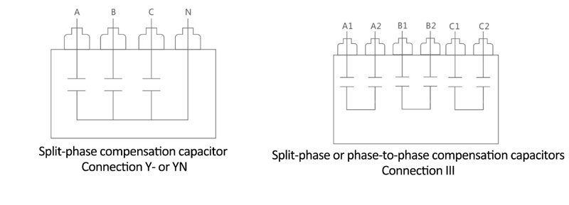
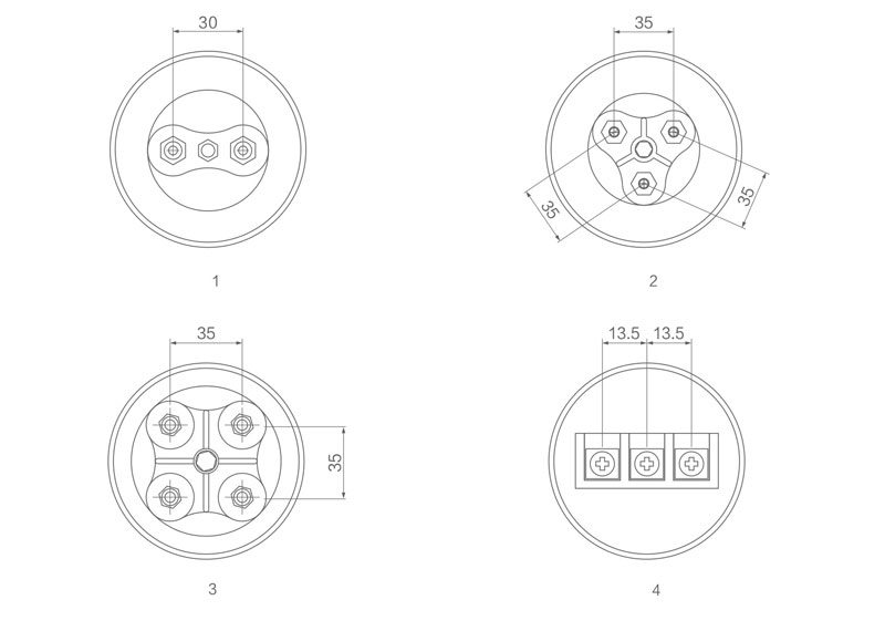
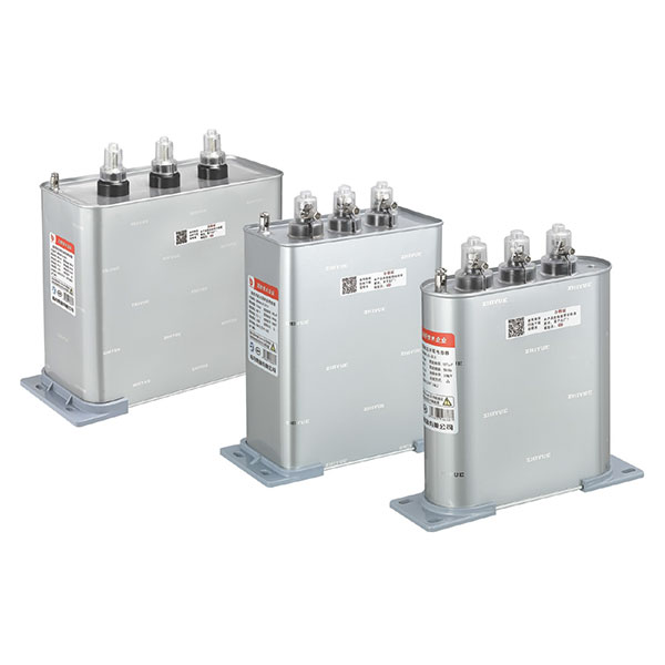
1.Three single-phase capacitors are connected in a Y configuration with the neutral point brought out (marked as the 'N' terminal) or III, thus forming three single-phase interconnected capacitors.
2.Each independent unit is equipped with its own discharge resistor for enhanced safety.
3.Any damage to individual units is reliably isolated with over-pressure isolation devices for secure disconnection.
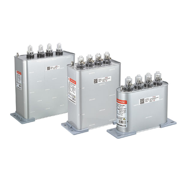
Note: Phase compensation can certainly also be achieved using three single-phase independent capacitor units. This section highlights the advantages of the three interconnected single-phase capacitors, including their compact size and convenient usage, making them highly favored by users.
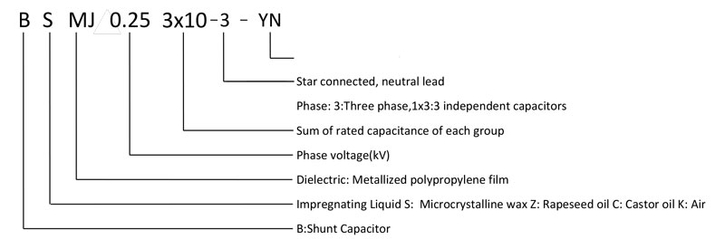
| SPECIFICATION | RATED VOLTAGE (kV) Un |
RATED CAPACITY (kVAR) Qn |
RATED CAPACITY (kVAR) Cn |
RATED CURRENT (A) In |
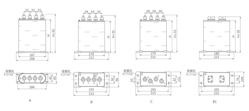
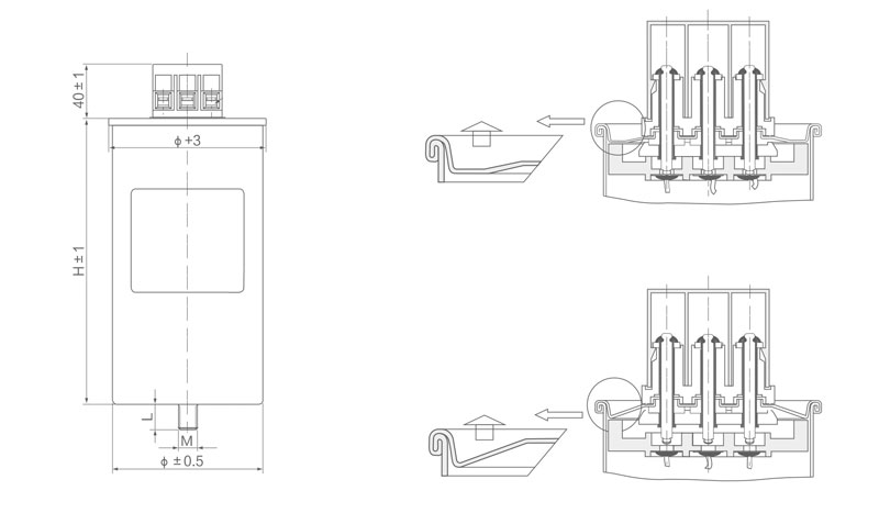
HEIGHT H(mm) |
| 0.23-3x1-3YN | 0.23 | 3 | 180.6 | 4.3 | 125 |
| 0.23-3x1.67-3YN | 0.23 | 5 | 301.0 | 7.2 | 125 |
| 0.23-3x2-3YN | 0.23 | 6 | 361.2 | 8.7 | 125 |
| 0.23-3x2.5-3YN | 0.23 | 7.5 | 451.5 | 10.9 | 180 |
| 0.23-3x2.7-3YN | 0.23 | 8 | 481.6 | 11.6 | 180 |
| 0.23-3x3.3-3YN | 0.23 | 10 | 602.0 | 14.5 | 180 |
| 0.23-3x4-3YN | 0.23 | 12 | 722.4 | 17.4 | 210 |
| 0.23-3x4.7-3YN | 0.23 | 14 | 842.8 | 20.3 | 210 |
| 0.23-3x5-3YN | 0.23 | 15 | 903.0 | 21.7 | 210 |
| 0.23-3x5.3-3YN | 0.23 | 16 | 963.2 | 23.2 | 210 |
| 0.23-3x6-3YN | 0.23 | 18 | 1083.6 | 26.1 | 210 |
| 0.23-3x6.67-3YN | 0.23 | 20 | 1204.1 | 29.0 | 210 |
| 0.23-3x8.3-3YN | 0.23 | 25 | 1505.1 | 36.2 | 260 |
| 0.23-3x10⁻³YN | 0.23 | 30 | 1806.1 | 43.5 | 310 |
| 0.25-3x1-3YN | 0.25 | 3 | 152.9 | 4.0 | 125 |
| 0.25-3x1.67-3YN | 0.25 | 5 | 254.8 | 6.7 | 125 |
| 0.25-3x2-3YN | 0.25 | 6 | 305.7 | 8.0 | 125 |
| 0.25-3x2.5-3YN | 0.25 | 7.5 | 382.2 | 10.0 | 125 |
| 0.25-3x2.7-3YN | 0.25 | 8 | 407.6 | 10.7 | 125 |
| 0.25-3x3.3-3YN | 0.25 | 10 | 509.6 | 13.3 | 180 |
| 0.25-3x4-3YN | 0.25 | 12 | 611.5 | 16.0 | 180 |
| 0.25-3x4.7-3YN | 0.25 | 14 | 713.4 | 18.7 | 210 |
| 0.25-3x5-3YN | 0.25 | 15 | 764.3 | 20.0 | 210 |
| 0.25-3x5.3-3YN | 0.25 | 16 | 815.3 | 21.3 | 210 |
| 0.25-3x6-3YN | 0.25 | 18 | 917.2 | 24.0 | 210 |
| 0.25-3x6.67-3YN | 0.25 | 20 | 1019.1 | 26.7 | 210 |
| 0.25-3x8.3-3YN | 0.25 | 25 | 1273.9 | 33.3 | 210 |
| 0.25-3x10⁻³YN | 0.25 | 30 | 1528.7 | 40.0 | 260 |
| 0.25-3x13.3-3YN | 0.25 | 40 | 2038.2 | 53.3 | 310 |
| 0.28-3x1-3YN | 0.28 | 3 | 121.9 | 3.6 | 125 |
| 0.28-3x1.67-3YN | 0.28 | 5 | 203.1 | 6.0 | 125 |
| 0.28-3x2-3YN | 0.28 | 6 | 243.7 | 7.1 | 125 |
| 0.28-3x2.5-3YN | 0.28 | 7.5 | 304.7 | 8.9 | 125 |
| 0.28-3x2.7-3YN | 0.28 | 8 | 325.0 | 9.5 | 125 |
| 0.28-3x3.3-3YN | 0.28 | 10 | 406.2 | 11.9 | 180 |
| 0.28-3x4-3YN | 0.28 | 12 | 487.5 | 14.3 | 180 |
| 0.28-3x4.7-3YN | 0.28 | 14 | 568.7 | 16.7 | 210 |
| 0.28-3x5-3YN | 0.28 | 15 | 609.3 | 17.9 | 210 |
| 0.28-3x5.3-3YN | 0.28 | 16 | 649.9 | 19.0 | 210 |
| 0.28-3x6-3YN | 0.28 | 18 | 731.2 | 21.4 | 210 |
| 0.28-3x6.67-3YN | 0.28 | 20 | 812.4 | 23.8 | 210 |
| 0.28-3x8.3-3YN | 0.28 | 25 | 1015.5 | 29.8 | 210 |
| 0.28-3x10⁻³YN | 0.28 | 30 | 1218.6 | 35.7 | 260 |
| 0.28-3x13.3-3YN | 0.28 | 40 | 1624.9 | 47.6 | 310 |
| 0.3-3x1-3YN | 0.3 | 3 | 106.2 | 3.3 | 125 |
| 0.3-3x1.67-3YN | 0.3 | 5 | 176.9 | 5.6 | 125 |
| 0.3-3x2-3YN | 0.3 | 6 | 212.3 | 6.7 | 125 |
| 0.3-3x2.5-3YN | 0.3 | 7.5 | 265.4 | 8.3 | 125 |
| 0.3-3x2.7-3YN | 0.3 | 8 | 283.1 | 8.9 | 125 |
| 0.3-3x3.3-3YN | 0.3 | 10 | 353.9 | 11.1 | 180 |
| 0.3-3x4-3YN | 0.3 | 12 | 424.6 | 13.3 | 180 |
| 0.3-3x4.7-3YN | 0.3 | 14 | 495.4 | 15.6 | 180 |
| 0.3-3x5-3YN | 0.3 | 15 | 530.8 | 16.7 | 180 |
| 0.3-3x5.3-3YN | 0.3 | 16 | 566.2 | 17.8 | 210 |
| 0.3-3x6-3YN | 0.3 | 18 | 636.9 | 20.0 | 210 |
| 0.3-3x6.67-3YN | 0.3 | 20 | 707.7 | 22.2 | 210 |
| 0.3-3x8.3-3YN | 0.3 | 25 | 884.6 | 27.8 | 210 |
| 0.3-3x10⁻³YN | 0.3 | 30 | 1061.6 | 33.3 | 260 |
| 0.3-3x13.3-3YN | 0.3 | 40 | 1415.4 | 44.4 | 310 |
| 0.45-6-1x3 | 0.45 | 6 | 94.3 | 4.4 | 210 |
| 0.45-9-1x3 | 0.45 | 9 | 141.5 | 6.7 | 210 |
| 0.45-15-1x3 | 0.45 | 15 | 235.8 | 11.1 | 210 |
| 0.45-21-1x3 | 0.45 | 21 | 330.1 | 15.5 | 210 |
| 0.45-30-1x3 | 0.45 | 30 | 471.5 | 22.2 | 210 |
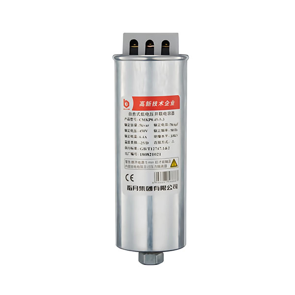
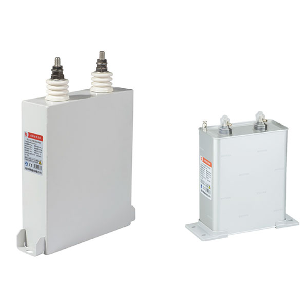
Cylindrical Phase Separation
If you have any enquiry about quotation or cooperation,please free to email us at niki@zhiyue.com or use the following enquiry form,Our sales representative will contact you within 24 hous.thank you for your interest in our products.
 English
 Espanol
 Pусский
 Deutsch
 简体中文
简体中文

 Message
 Cell Phones
 Telephone
 E-mail