
Since 1991

Power Factor Correction Capacitors are suitable for low-voltage power systems with a frequency of 50Hz or 60Hz. They are primarily used to improve power factor, reduce reactive power loss, enhance grid quality, and maximize transformer capacity, among other benefits.
Rated Voltage: 230V, 400V, 450V, 480V, 525V, 690V, 750V, 1200V, other custom voltages available;
Rated Capacity: 1kvar to 60kvar for 0.4~0.69kV, other custom capacities available;
Rated Frequency: 50Hz or 60Hz;
Summary
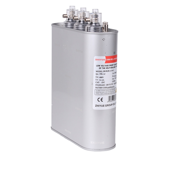
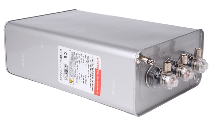
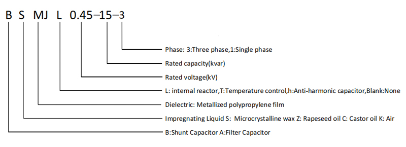
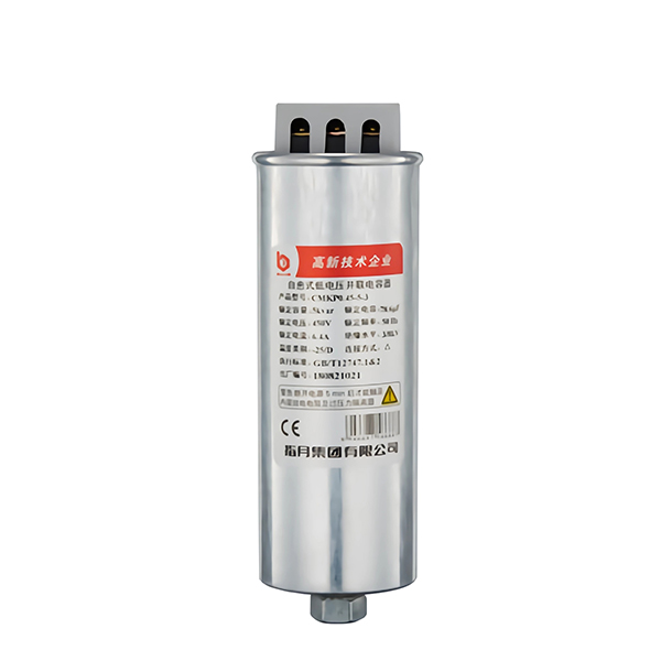
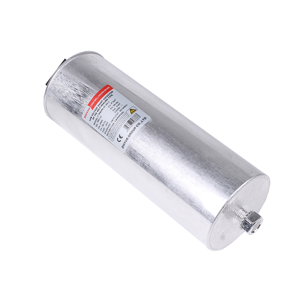
Power Factor Correction Capacitors
Optimize Energy, Enhance Efficiency, Create a Green Future
To meet the electrical energy demands of modern industries and businesses, we proudly introduce Power Factor Correction Capacitors that adhere to the International Electrotechnical Commission (IEC) standard 60831.
The Power Factor Correction Capacitors are widely applicable in industrial, commercial, and public sectors. Whether in manufacturing, construction, or the energy sector, our products assist you in efficiently managing energy consumption, reducing system losses, and thereby saving costs.
Why power factor is more than just a number──The importance of power factor.
Simply defined, power factor is a way to measure the efficiency of an electrical system. Expressed numerically, power factor is the ratio of working power to apparent power, with the ideal calculation represented as 1.0. Numbers aside, the most critical thing to recognize is that a load with a power factor of 1.0 results in the most efficient operation. However, many industrial and commercial electrical systems have a lower power factor, which means organizations are not fully utilizing the electrical power that they’re paying for. In these instances, additional energy is needed to operate the load, requiring the utility to provide more current. This additional power translates to fees and/or penalties levied by utility providers to customers with three-phase services; residential customers are never penalized.
When system efficiency is improved, it reduces the amount of energy that is required from the utility, which in turn can lower or eliminate costly penalties and fees. One of the most simple and cost-effective ways to achieve this is by installing power-factor-correction capacitors.
General Description:
Power Factor Correction Capacitors are suitable for low-voltage power systems with a frequency of 50Hz or 60Hz. They are primarily used to improve power factor, reduce reactive power loss, enhance grid quality, and maximize transformer capacity, among other benefits.
Technical data:
1.Rated Voltage: 230V, 400V, 450V, 480V, 525V, 690V, 750V, 1200V, other custom voltages available;
2.Rated Capacity: 1kvar to 60kvar for 0.4~0.69kV, other custom capacities available;
3.Rated Frequency: 50Hz or 60Hz;
4.Capacity Tolerance: -5% to +10%;
5.Loss Tangent: tanφ≤0.1% at 20℃;
6.Voltage Withstand: Between terminals withstands 2.15 times the rated voltage for 5 seconds, between terminals and shell withstands 2Un + 2kV or 3kV, whichever is higher, for 10 seconds without permanent breakdown or flashover;
7.Maximum Allowable Overvoltage: Up to 8 hours within 24 hours at 1.1 times the rated voltage; up to 30 minutes within 24 hours at 1.15 times the rated voltage; up to 5 minutes at 1.2 times the rated voltage; up to 1 minute at 1.3 times the rated voltage;
8.Max. Allowable Current: Operation at current up to 1.3 times the rated current is allowed. Transient overcurrent not exceeding 1.43 times the rated current;
9.Connection: Various connection methods including delta (Δ), Y-star (Y), -Y with neutral point lead-out, III three-phase segment, single-phase, and other configurations;
10.Self-discharge Performance: After capacitor disconnection, residual voltage drops from √2Un to below 50V within 3 minutes;
11.Service Life: Continuous operation time ≥ 100,000 hours under standard operating conditions;
12.Standard: IEC 60831.
Characteristics:
·Small size, light weight, easy to install
Using high-quality high-temperature resistant metallized polypropylene film new material as the medium, the unique structural design makes the capacitor volume and weight only 1/4 and 1/4 of the old product.
·Low loss, less heat, low temperature rise
Using a new gold spraying process and a unique metallized film edge thickening technology, the capacitor's ability to withstand inrush current is enhanced, its performance is stable, its working life is extended, and the energy consumption of the capacitor itself is reduced.
·Excellent self-healing performance medium
Local breakdown can heal itself quickly.
·New explosion-proof design, safe and reliable
Built-in self-discharge resistor and new patented explosion-proof device, safe and reliable to use.
·Dry structure, no oil leakage, safe and environmentally friendly
It is made of microcrystalline wax, which is solid at room temperature and has a melting point higher than 70°C. It can be impregnated under high vacuum.
·Corrosion-resistant and anti-counterfeiting metal shell, beautiful and sturdy
The metal shell has undergone special double anti-corrosion treatment to improve corrosion resistance.
| SPECIFICATION | RATED VOLTAGE(kV) Un |
RATED CAPACITY(kVAR) Qn |
RATED CAPACITY(kVAR) Cn |
RATED CURRENT(A) In |
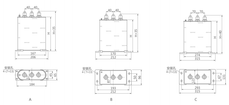
HEIGHT H(mm) |
TERMINAL | SHELL |
| 0.4-5-3 | 0.4 | 5 | 99.5 | 7.2 | 125 | M6 | A |
| 0.4-6-3 | 0.4 | 6 | 119.4 | 8.7 | 125 | M6 | A |
| 0.4-7.5-3 | 0.4 | 7.5 | 149.3 | 10.8 | 125 | M6 | A |
| 0.4-8-3 | 0.4 | 8 | 159.2 | 11.5 | 125 | M6 | A |
| 0.4-10-3 | 0.4 | 10 | 199.0 | 14.4 | 180 | M6 | A |
| 0.4-12-3 | 0.4 | 12 | 238.9 | 17.3 | 180 | M6 | A |
| 0.4-14-3 | 0.4 | 14 | 278.7 | 20.2 | 180 | M6 | A |
| 0.4-15-3 | 0.4 | 15 | 298.6 | 21.7 | 210 | M6 | A |
| 0.4-16-3 | 0.4 | 16 | 318.5 | 23.1 | 210 | M6 | A |
| 0.4-18-3 | 0.4 | 18 | 358.3 | 26.0 | 210 | M6 | A |
| 0.4-20-3 | 0.4 | 20 | 398.1 | 28.9 | 210 | M6 | B |
| 0.4-22-3 | 0.4 | 22 | 437.9 | 31.8 | 210 | M8 | B |
| 0.4-24-3 | 0.4 | 24 | 477.7 | 34.6 | 210 | M8 | B |
| 0.4-25-3 | 0.4 | 25 | 497.6 | 36.1 | 210 | M8 | B |
| 0.4-28-3 | 0.4 | 28 | 557.3 | 40.4 | 260 | M8 | B |
| 0.4-30-3 | 0.4 | 30 | 597.1 | 43.3 | 260 | M8 | B |
| 0.4-35-3 | 0.4 | 35 | 696.7 | 50.5 | 260 | M8 | B |
| 0.4-40-3 | 0.4 | 40 | 796.2 | 57.7 | 310 | M8 | B |
| 0.4-45-3 | 0.4 | 45 | 895.7 | 65.0 | 310 | M8 | B |
| 0.4-50-3 | 0.4 | 50 | 995.2 | 72.2 | 230 | M10 | C |
| 0.4-55-3 | 0.4 | 55 | 1094.7 | 79.4 | 230 | M10 | C |
| 0.4-60-3 | 0.4 | 60 | 1194.3 | 86.6 | 230 | M10 | C |
| 0.45-5-3 | 0.45 | 5 | 78.6 | 6.4 | 125 | M6 | A |
| 0.45-6-3 | 0.45 | 6 | 94.4 | 7.7 | 125 | M6 | A |
| 0.45-7.5-3 | 0.45 | 7.5 | 118.0 | 9.6 | 125 | M6 | A |
| 0.45-8-3 | 0.45 | 8 | 125.8 | 10.3 | 125 | M6 | A |
| 0.45-10-3 | 0.45 | 10 | 157.3 | 12.8 | 125 | M6 | A |
| 0.45-12-3 | 0.45 | 12 | 188.7 | 15.4 | 180 | M6 | A |
| 0.45-14-3 | 0.45 | 14 | 220.2 | 18.0 | 180 | M6 | A |
| 0.45-15-3 | 0.45 | 15 | 235.9 | 19.2 | 180 | M6 | A |
| 0.45-16-3 | 0.45 | 16 | 251.6 | 20.5 | 180 | M6 | A |
| 0.45-18-3 | 0.45 | 18 | 283.1 | 23.1 | 180 | M6 | A |
| 0.45-20-3 | 0.45 | 20 | 314.5 | 25.7 | 210 | M6 | A |
| 0.45-22-3 | 0.45 | 22 | 346.0 | 28.2 | 210 | M6 | A |
| 0.45-24-3 | 0.45 | 24 | 377.4 | 30.8 | 210 | M8 | B |
| 0.45-25-3 | 0.48 | 25 | 345.6 | 30.1 | 210 | M8 | B |
| 0.45-28-3 | 0.48 | 28 | 387.0 | 33.7 | 210 | M8 | B |
| 0.45-30-3 | 0.48 | 30 | 414.7 | 36.1 | 210 | M8 | B |
| 0.45-35-3 | 0.48 | 35 | 483.8 | 42.1 | 260 | M8 | B |
| 0.45-40-3 | 0.48 | 40 | 552.9 | 48.1 | 260 | M8 | B |
| 0.45-45-3 | 0.48 | 45 | 622.0 | 54.1 | 260 | M8 | B |
| 0.45-50-3 | 0.48 | 50 | 691.1 | 60.1 | 310 | M8 | B |
| 0.45-55-3 | 0.48 | 55 | 760.2 | 66.2 | 310 | M8 | B |
| 0.45-60-3 | 0.48 | 60 | 829.4 | 72.2 | 230 | M10 | C |
| 0.48-5-3 | 0.48 | 5 | 69.1 | 6.0 | 125 | M6 | A |
| 0.48-10-3 | 0.48 | 10 | 138.2 | 12.0 | 125 | M6 | A |
| 0.48-15-3 | 0.48 | 15 | 207.3 | 18.0 | 180 | M6 | A |
| 0.48-20-3 | 0.48 | 20 | 276.5 | 24.1 | 210 | M6 | A |
| 0.48-25-3 | 0.48 | 25 | 345.6 | 30.1 | 210 | M8 | B |
| 0.48-30-3 | 0.48 | 30 | 414.7 | 36.1 | 210 | M8 | B |
| 0.48-35-3 | 0.48 | 35 | 483.8 | 42.1 | 260 | M8 | B |
| 0.48-40-3 | 0.48 | 40 | 552.9 | 48.1 | 260 | M8 | B |
| 0.48-45-3 | 0.48 | 45 | 622.0 | 54.1 | 310 | M8 | B |
| 0.48-50-3 | 0.48 | 50 | 691.1 | 60.1 | 310 | M8 | B |
| 0.48-55-3 | 0.48 | 55 | 760.2 | 66.2 | 310 | M8 | B |
| 0.48-60-3 | 0.48 | 60 | 829.4 | 72.2 | 230 | M10 | C |
| 0.525-5-3 | 0.525 | 5 | 57.8 | 5.5 | 125 | M6 | A |
| 0.525-10-3 | 0.525 | 10 | 115.5 | 11.0 | 125 | M6 | A |
| 0.525-15-3 | 0.525 | 15 | 173.3 | 16.5 | 180 | M6 | A |
| 0.525-16-3 | 0.525 | 16 | 184.9 | 17.6 | 180 | M6 | A |
| 0.525-18-3 | 0.525 | 18 | 208.0 | 19.8 | 210 | M6 | A |
| 0.525-20-3 | 0.525 | 20 | 231.1 | 22.0 | 210 | M6 | A |
| 0.525-25-3 | 0.525 | 25 | 288.9 | 27.5 | 210 | M8 | B |
| 0.525-30-3 | 0.525 | 30 | 346.6 | 33.0 | 210 | M8 | B |
| 0.525-40-3 | 0.525 | 40 | 462.2 | 44.0 | 310 | M8 | B |
| 0.525-50-3 | 0.525 | 50 | 577.7 | 55.0 | 230 | M10 | C |
| 0.525-60-3 | 0.525 | 60 | 693.3 | 66.0 | 280 | M10 | C |
| 0.69-5-3 | 0.69 | 5 | 33.4 | 4.2 | 125 | M6 | A |
| 0.69-10-3 | 0.69 | 10 | 66.9 | 8.4 | 210 | M6 | A |
| 0.69-15-3 | 0.69 | 15 | 100.3 | 12.6 | 210 | M6 | A |
| 0.69-16-3 | 0.69 | 16 | 107.0 | 13.4 | 210 | M6 | A |
| 0.69-20-3 | 0.69 | 20 | 133.8 | 16.7 | 210 | M6 | B |
| 0.69-25-3 | 0.69 | 25 | 167.2 | 20.9 | 210 | M8 | B |
| 0.69-30-3 | 0.69 | 30 | 200.7 | 25.1 | 260 | M8 | B |
| 0.69-40-3 | 0.69 | 40 | 267.6 | 33.5 | 230 | M10 | C |
| 0.69-50-3 | 0.69 | 50 | 334.5 | 41.8 | 230 | M10 | C |
| 0.69-60-3 | 0.69 | 60 | 401.4 | 50.2 | 280 | M10 | C |
| 1.2-5-3 | 1.2 | 5 | 11.1 | 2.4 | 125 | M6 | A |
| 1.2-10-3 | 1.2 | 10 | 22.1 | 4.8 | 210 | M6 | A |
| 1.2-15-3 | 1.2 | 15 | 33.2 | 7.2 | 210 | M6 | A |
| 1.2-20-3 | 1.2 | 20 | 44.2 | 9.6 | 210 | M6 | B |
| 1.2-25-3 | 1.2 | 25 | 55.3 | 12.0 | 210 | M8 | B |
| 1.2-30-3 | 1.2 | 30 | 66.3 | 14.4 | 260 | M8 | B |
| 1.2-40-3 | 1.2 | 40 | 88.5 | 19.2 | 310 | M8 | B |
| 1.2-50-3 | 1.2 | 50 | 110.6 | 24.1 | 230 | M10 | C |
| 1.4-10-3 | 1.4 | 10 | 16.2 | 4.1 | 210 | M6 | A |
| 1.4-15-3 | 1.4 | 15 | 24.4 | 6.2 | 210 | M6 | A |
| 1.4-20-3 | 1.4 | 20 | 32.5 | 8.2 | 210 | M6 | B |
| 1.4-25-3 | 1.4 | 25 | 40.6 | 10.3 | 210 | M8 | B |
| 1.4-30-3 | 1.4 | 30 | 48.7 | 12.4 | 260 | M8 | B |
| 1.4-40-3 | 1.4 | 40 | 65.0 | 16.5 | 310 | M8 | B |
| 1.4-50-3 | 1.4 | 50 | 81.2 | 20.6 | 230 | M10 | C |
| 1.4-60-3 | 1.4 | 60 | 97.5 | 24.7 | 280 | M10 | C |
If you have any enquiry about quotation or cooperation,please free to email us at niki@zhiyue.com or use the following enquiry form,Our sales representative will contact you within 24 hous.thank you for your interest in our products.
 English
 Espanol
 Pусский
 Deutsch
 简体中文
简体中文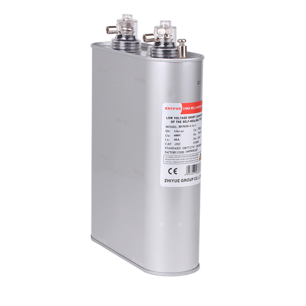

 Message
 Cell Phones
 Telephone
 E-mail